ESPHome Fan Controller: PID Smart Fan for ESP32
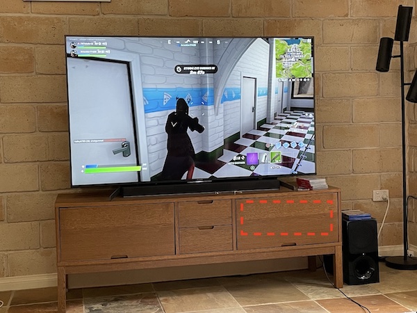
The closed media cabinet this project was built to cool, housing a PS5, Mac mini, Raspberry Pi, and other devices
- ESP32 (NodeMCU compatible)
- DHT11 temperature and humidity sensor (3-pin module)
- 12V PWM 4-pin computer fan (120mm)
- LM2596 buck converter
- 12V power adapter (1A or 2A)
- 12V DC female jack
- Jumper wires
What You Will Build
This project builds a whisper-quiet, thermostat-controlled fan system for any enclosed space — a media console stuffed with a game console and a Mac mini, a networking cabinet full of routers and switches, or any other box that traps heat.
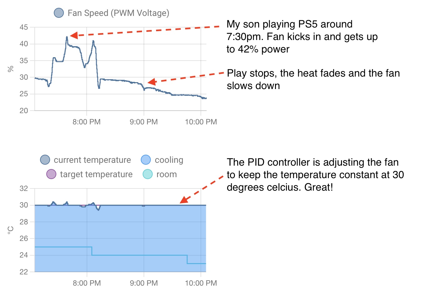
The problem with a plain on/off thermostat is that the fan cycles loudly and unpredictably. This build uses PID (Proportional-Integral-Derivative) control — the same feedback algorithm used in industrial process control — to smoothly dial in exactly the right fan speed to hold your chosen temperature. Instead of slamming the fan on at full blast, the controller might settle at 22% power and stay there silently all evening.
The ESP32 runs ESPHome firmware and reports to Home Assistant over WiFi, but it is fully standalone: if your network goes down, the cooling keeps working. One ESP32 can manage up to 10 independent enclosures, each with its own temperature sensor and fan, limited only by the 10 PWM-capable output pins on the board.
 \2
\2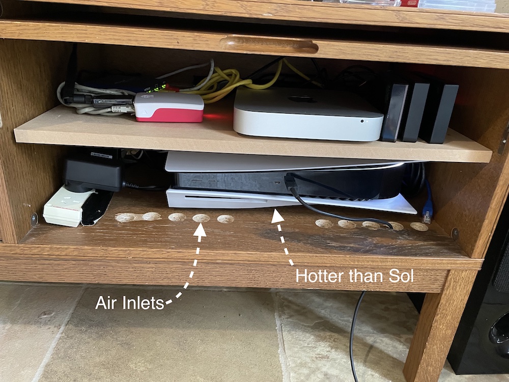 \2
\2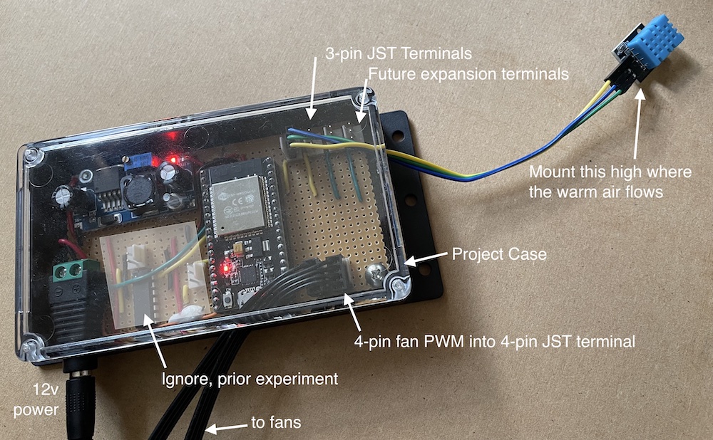 \2
\2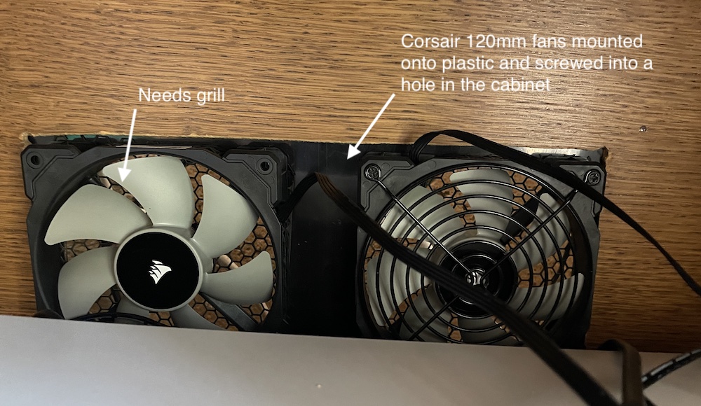 \2
\2Parts and Tools
The full electronic parts list comes to approximately $29 USD. You will also need a multimeter.
| Part | Notes |
|---|---|
| ESP32 (NodeMCU compatible) | Any ESP32 board works; NodeMCU used in the guide |
| DHT11 temperature and humidity sensor | Use the 3-pin board version |
| 12V PWM 4-pin computer fan | Corsair or Noctua recommended; must be 4-pin PWM |
| LM2596 buck converter | Steps 12V down to 3.3V for the ESP32 |
| 12V power adapter | 1A or 2A depending on fan current draw |
| 12V DC female jack | Often bundled with the power adapter |
| Jumper wires | Standard breadboard-style wires |
| Multimeter | Required to calibrate buck converter output to exactly 3.3V |
Critical fan note: You need a 4-pin PWM fan. 3-pin fans are simple on/off and will not work with this controller. Corsair and Noctua fans are confirmed to stop spinning at 0% PWM duty cycle as expected. Some other brands do not behave correctly at the extremes — the repository documents a MOSFET workaround if you encounter this.
On the software side you need ESPHome installed (either as a Home Assistant add-on or via the command line) and a clone of this repository.
Typical use cases
Keep a closed TV cabinet cool when it houses a game console, streaming device, and mini PC running simultaneously — without disruptive fan cycling on movie nights.
Replace a simple on/off fan switch with smooth, proportional speed control that holds a precise target temperature by settling at just the right power level.
Maintain safe operating temperatures in an enclosed rack or cupboard full of routers, switches, and patch panels, with automatic adjustment as load changes.
Monitor live temperature graphs, adjust the target setpoint, and tune PID gains from a Lovelace dashboard without recompiling or reflashing the ESP32.
How the PID Controller Works
The DHT11 reports temperature to the ESP32 on a regular interval. ESPHome's PID climate component compares the live reading to your target temperature and computes three correction terms:
- P (Proportional): reacts immediately to the current gap between measured and target temperature
- I (Integral): corrects for persistent offset that the P term alone cannot eliminate over time
- D (Derivative): damps rapid changes to prevent the controller from overshooting
The combined PID output drives the ESP32's LEDC peripheral, which generates a 25 kHz PWM signal on the fan GPIO — the standard frequency for PC fans, chosen to minimize audible buzzing.
Because DHT11 readings are slightly noisy, an exponential moving average filter smooths the sensor data before it reaches the PID. Without this filter the controller reacts to every minor fluctuation and the fan speed chatters.
The three gain values — kp, ki, and kd — are exposed to Home Assistant as live input fields, so you can tune the controller's behavior without recompiling or reflashing firmware.
Wiring the Hardware
Follow the wiring diagram in the repository. The key connections are:
- Buck converter output: Use a screwdriver to adjust the LM2596 trimmer until your multimeter reads exactly 3.3V on the output — before connecting the ESP32.
- Ground loop: Connect the 12V ground and the 3.3V (ESP32) ground together. This is the most common build mistake. At least five different builders have reported their fan spinning continuously because they skipped this step.
- Fan PWM wire: Connect to any ESP32 GPIO capable of output. GPIOs 34–39 cannot generate PWM output, so avoid those for the fan.
- DHT11 data pin: Connect to a free GPIO (GPIO33 in the example config).
- Tachometer wire (optional): The fan's blue tach wire can connect to a PWM-capable input GPIO (GPIO25 in the example) for live RPM monitoring and stuck-rotor detection. One input pin per fan is required if you use this feature.
If you want to skip the buck converter entirely, you can power the ESP32 from a separate 3.3V or 5V source and keep the 12V supply dedicated to the fan — just remember to still join the grounds.
Flash and Configure
1. Clone the repository
git clone https://github.com/patrickcollins12/esphome-fan-controller.git
cd esphome-fan-controller
2. Set your WiFi credentials
mv secrets-sample.yaml secrets.yaml
Edit secrets.yaml with your SSID and password. The .gitignore keeps this file out of any accidental commits.
3. Edit config-fan.yaml
Change the device name from console-fan to something meaningful. Then set the correct GPIO pins for your wiring.
Temperature sensor with the smoothing filter:
- platform: dht
  pin: GPIO33
  temperature:
    name: "Temperature"
    id: console_fan_temperature
    accuracy_decimals: 3
    filters:
       - exponential_moving_average:
           alpha: 0.1
           send_every: 1
PWM fan output at 25 kHz:
- platform: ledc
  id: console_heat_speed
  pin: GPIO27
  frequency: "25000 Hz"
  min_power: 13%
  max_power: 80%
The min_power and max_power values in the example reflect one specific fan (Corsair, stops spinning below 13%). Adjust these for your fan and noise tolerance.
4. Install ESPHome
pip3 install esphome
Alternatively, use the ESPHome add-on inside Home Assistant.
5. Flash the firmware
Connect your ESP32 via USB, then run:
esphome run console-fan.yaml
6. Verify it is running
esphome logs console-fan.yaml
You should see DHT11 temperature readings and PID output values streaming in the log. If the fan spins at full speed and won't slow down, check that your 12V and 3.3V grounds are joined.
Home Assistant Setup and Ideas to Extend
Once the ESP32 is on your network, Home Assistant will auto-discover the device. Add it, then import the Lovelace dashboard from lovelace-dashboard.yaml in the repository. The dashboard provides:
- A thermostat card to set your target temperature and toggle the fan on or off
- Live graphs of temperature and fan speed over time
- PID diagnostic values: P term, I term, D term, error, output, and deadband status
- A manual fan speed override that bypasses PID entirely
- Live kp, ki, kd input fields for on-the-fly tuning without a reflash
Ideas to extend the build:
- Add a second fan: Wire it to a second PWM GPIO output and duplicate the fan entry in the YAML. The ESP32 supports up to 10 fans across 10 independent enclosures.
- Average two sensors: If temperature varies across your enclosure, the repository shows how to average two DHT11 readings for a more representative input to the PID.
- Upgrade the sensor: A faster or more accurate sensor like a BME280 can replace the DHT11 — adjust the exponential moving average alpha to suit the faster update rate.
- Optional tachometer: Wiring the blue tach wire to an input GPIO lets you monitor actual RPM and detect a blocked or failed fan rotor.
- Raspberry Pi Pico W: The README notes this configuration also works on a Pico W with a board and platform change in the YAML.
Limitations to be aware of:
- 3-pin fans are not supported — only 4-pin PWM fans work.
- Some fans do not stop at 0% duty cycle or behave unexpectedly at 100%; a MOSFET workaround is documented in the repository's issue tracker.
- The 4-pin DHT11 variant may need a pull-up resistor (noted as untested in the README).
- PID gain tuning requires some experimentation for each specific fan and enclosure combination.
The ESPHome Fan Controller is a practical, well-documented build that replaces brute-force fan cycling with quiet, PID-driven speed control using nothing but a YAML file and a handful of inexpensive parts. With 749 stars and active community contributions since 2022, it has proven reliable across a wide range of enclosures and fan choices. The main friction points are selecting a compatible 4-pin PWM fan and correctly joining the 12V and 3.3V grounds — both are clearly flagged in the guide.
Sources
github.compatrickcollins12/esphome-fan-controller — repository & READMEFacts in this article come from the project's public README and GitHub metadata at the time of writing. Images belong to their respective owners and link back to the original source.