TNY-360: Build an Open-Source Quadruped Robot Dog with ESP32-S3
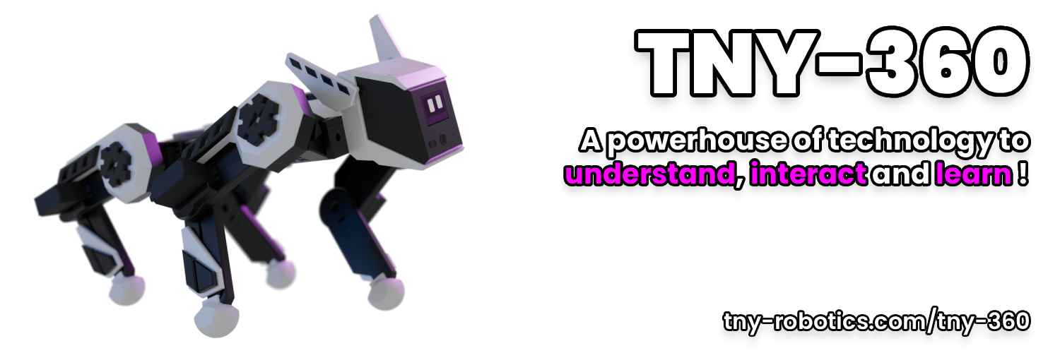
TNY-360 quadruped robot dog — open-source frame, custom PCBs, and 12 modified servos driven by an ESP32-S3.
- ESP32-S3 N16R8 Module
- 12x MG996R Servos (modified for analog position feedback)
- 2x MG90D Micro Servos (ears)
- PCA9685 16-Channel PWM Driver
- OV2640 Camera Module
- VL53L0X Time-of-Flight (Lidar) Sensor
- LSM6DS3 6-Axis IMU
- SSD1306 OLED Display (128x64)
- I2S MEMS Microphone
- I2S Speaker
- INA219 Voltage/Current Sensor
- 3S LiPo Battery (6x Samsung INR18650-25R cells)
- Custom Op-Amp Buffer PCB (servo feedback)
- Custom Control, Sensor, Brain, and Power PCBs
What You Will Build
The TNY-360 is a 12-servo quadruped robot dog — a four-legged walking machine you design, print, solder, and program yourself. Every part of the stack is open: the STL files for the body, the Gerber files for the PCBs, and the C++ firmware that runs on the ESP32-S3.
What makes it stand out from hobby servo projects is the closed-loop feedback system. Standard hobby servos are blind — you send a PWM pulse and hope the leg ended up where you wanted. The TNY-360 modifies MG996R servos with a custom Op-Amp buffer PCB that reads the servo's internal potentiometer without electrical noise, giving the firmware real-time position data at 200 Hz. The result is a robot that can detect and compensate for mechanical backlash and actuator lag at runtime.
The project is built for makers who want to understand the full system — electronics, mechanics, firmware, and motion control — not just assemble a kit.
What You Need
Hardware
The TNY-360 uses a purpose-built stack of components. Every part listed here comes from the official README and BOM.
Core compute and power
- ESP32-S3 N16R8 Module
- 3S LiPo Battery pack (6x Samsung INR18650-25R cells)
- INA219 Voltage/Current Sensor for battery monitoring
Actuators
- 12x MG996R Servos — must be modified with the Op-Amp buffer PCB for position feedback
- 2x MG90D Micro Servos for the ear mechanism
- PCA9685 16-Channel PWM Driver
Sensors and I/O
- OV2640 Camera Module
- VL53L0X Time-of-Flight sensor for distance measurement
- LSM6DS3 6-Axis IMU for orientation
- SSD1306 OLED Display (128x64)
- I2S MEMS Microphone and Speaker for audio
PCBs and Structure
- Custom PCBs: Control, Sensor, Brain, Power, and Op-Amp Buffer boards. Gerber files are in the
PCBs/directory; you order them from a PCB fabrication house. - 3D-printed frame: STL and 3MF files are in the
CAD/directory, ready for your printer. - JST cables and low-profile pin headers for inter-board connections.
Software
- ESP-IDF (Espressif IoT Development Framework) — the firmware build system
- PlatformIO — the project is structured as a PlatformIO workspace under
Firmware/ - TNY-Coder (optional) — a block-based web app by TNY Robotics for visual programming of the robot without touching C++ code
The full sourcing guide with links is at tny-robotics.com/docs/tny-360.
Typical use cases
The dual-core ESP32-S3 architecture runs a strict 200 Hz kinematics loop on one core and WebSocket communication on the other, making this a practical study in embedded real-time systems.
Ordering and assembling the custom Control, Sensor, Brain, Power, and Op-Amp buffer boards gives you hands-on experience with Gerber files, JST harnesses, and modular PCB design.
TNY-Coder lets students and beginners program walking behaviors through a browser-based block interface over WebSocket, with no firmware changes needed.
The Op-Amp position-feedback mod on MG996R servos is a reusable technique for any project that needs affordable closed-loop actuation without buying specialized hardware.
How It Works
The ESP32-S3 runs two parallel workloads on its two cores, and the firmware keeps them strictly separated:
Core 1 — "Reflex" runs a hard real-time kinematics and control loop at exactly 200 Hz. This core reads the position feedback from all 12 leg servos, runs the inverse kinematics calculations, applies backlash and latency compensation, and pushes new PWM targets to the PCA9685. Nothing else is allowed to interrupt this loop.
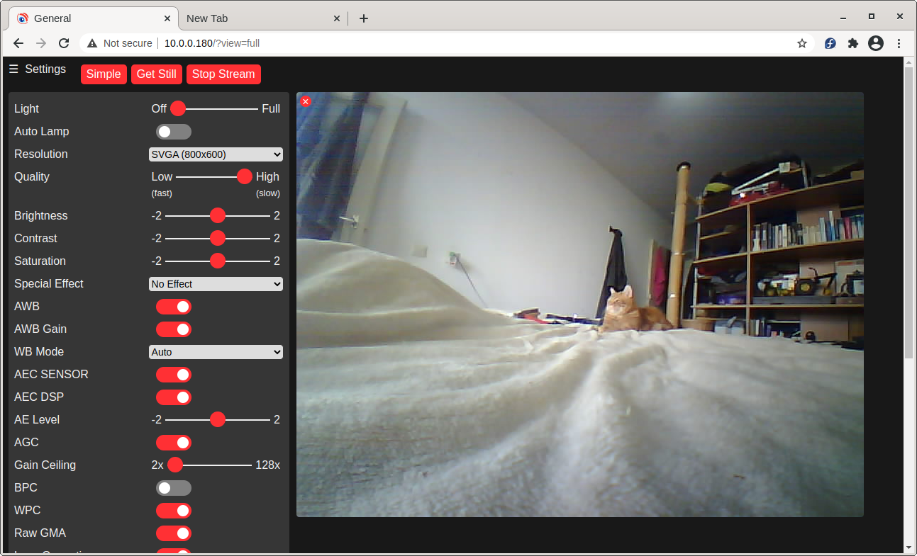
Core 0 — "Brain" handles everything that can tolerate variable timing: WebSocket communication with the browser UI or TNY-Coder app, OLED display updates, camera streaming from the OV2640, ToF distance readings from the VL53L0X, and IMU orientation from the LSM6DS3.
The servo modification is the most critical hardware step. A standard MG996R has an internal potentiometer that the servo's own control board reads. The Op-Amp buffer PCB taps that potentiometer output and conditions the analog signal so the ESP32-S3's ADC can read it cleanly without being corrupted by motor noise. This is what enables the 200 Hz closed loop — without feedback, the kinematics loop would be running open-eyed.
The modular PCB ecosystem (Control, Sensor, Brain, Power boards talking through JST cables) eliminates wiring harnesses and makes individual board replacement practical — a design choice aimed at both repairability and STEM education.
Build and Flash Steps
The TNY-360 build is documented in full detail on the official step-by-step guide at tny-robotics.com/docs/tny-360/build-it. Follow that guide for the authoritative assembly sequence. This section gives you a map of the major phases.
Phase 1 — Order parts and PCBs
Download the BOM from the BOM/ directory. Order the custom PCBs using the Gerber files from PCBs/. Source all components including the MG996R servos, ESP32-S3 module, sensors, and battery cells.
Phase 2 — Print the frame
Open the STL or 3MF files from CAD/ in your slicer. The official guide covers orientation and settings. Print all structural parts.
Phase 3 — Modify the servos This is the most involved hardware step. Each MG996R must be opened, and the Op-Amp buffer PCB must be installed to expose clean analog position feedback. The full procedure is documented in the Servo Modding Tutorial.
Phase 4 — Assemble electronics Mount the custom PCBs, connect boards via JST cables and pin headers, and install the sensors. The modular layout means each board has a defined slot; there is no free-form wiring.
Phase 5 — Flash the firmware
The firmware lives in Firmware/ as a PlatformIO project written in C++ against ESP-IDF. Open the project in PlatformIO, connect your ESP32-S3, and use PlatformIO's build and upload commands. Custom sensor and actuator drivers are under Firmware/components/.
Phase 6 — Calibrate The firmware includes a smart auto-calibration routine. Mechanical endstops validate assembly, and runtime algorithms compensate for servo backlash and latency. Run calibration before attempting any walking gaits.
Phase 7 — Program and move Use TNY-Coder to send commands over WebSocket from a browser without writing code, or extend the C++ firmware directly for custom behaviors. The dorsal expansion port exposes I2C and power for add-on modules.
Ideas to Extend It and Known Limitations
Extensions the hardware is ready for
- Vision processing: The OV2640 camera streams over WebSocket. You can pipe frames to a companion computer or a cloud inference endpoint for object detection or person tracking.
- Voice interaction: The I2S microphone and speaker are wired in. Adding wake-word detection or a TTS pipeline via the Brain core is a natural next step.
- Custom hardware modules: The dorsal I2C/Power expansion port is designed for add-on boards. Attach additional sensors, a second display, or custom actuators without modifying the main PCBs.
- Block-based curriculum: TNY-Coder turns the robot into a STEM teaching platform. Students can program gaits and reactions without touching firmware code.
- Gait research: With position feedback at 200 Hz and an IMU, the platform is suitable for experimenting with dynamic gaits, terrain adaptation, and basic reinforcement learning policies run on an external machine.
Limitations to be aware of
- The servo modification requires soldering inside a small enclosure and basic electronics knowledge. It is not optional — without the Op-Amp PCB the closed-loop control does not function.
- V2 CAD files, PCBs, and BOM are listed as "coming soon" in the repository at time of writing. V1 files are available; check the repository for V2 availability before ordering.
- The license is CC BY-NC-SA 4.0 — non-commercial use only. You cannot sell the robot or derivatives without contacting TNY Robotics.
- With 31 open issues, some firmware areas are still being refined. The Discord and GitHub Issues tracker are the right places to report problems or ask for help.
The TNY-360 is one of the most complete open-source quadruped projects available for the ESP32 platform — full mechanical CAD, custom PCBs, and a well-structured ESP-IDF firmware all in one repository. The servo modification and multi-board electronics assembly make this an Advanced build, but the payoff is a robot with genuine closed-loop motion control that you understand end to end. If you can solder, run a 3D printer, and are comfortable with PlatformIO, this is a rewarding and educational long-form build.
Sources
github.comTNY-Robotics/TNY-360 — repository & README tny-robotics.comOfficial websiteFacts in this article come from the project's public README and GitHub metadata at the time of writing. Images belong to their respective owners and link back to the original source.